 |
AFR combustion chamber pretty much finished at this point. You can see that this is also a development port by the way that the bowls are shaped. |
 |
This is the chamber and bowls as delivered from AFR with their expensive CNC option. Looking back, I would have skipped that costly waste of money and just ordered them basic. Steve does a much better job and it would have cost a lot less in the end. Live and learn. |
 |
Port on the left is in development. It has been welded already and has the roof raised. The one on the right is as delivered from AFR. |
 |
Big end of the Oliver 5.850" long connecting rod. |
 |
The whole rod. These are about the strongest and most reliable steel rods money can buy. Billet. |
 |
Another big end shot. Shows how beefy they are. |
 |
Last rod shot shows how they are optimized for strength where they are most likely to break-right at the bottom of the bolt head. |
 |
Looking at the Crower billet hydraulic lifters. Much stronger than OE lifters and should provide better valve control at high rpms. |
 |
Showing the plunger with it's custom annular bleed holes. Different than any I have ever seen, but then I haven't seen that many hydraulic lifters. |
 |
Interesting profile maximized for strength. Also note the size of the roller axles. They should never give any trouble with a street cam. |
 |
Final view kind of shows everything at once. Very nice lifters. |
 |
This is what you refer to if you want to email Brian Crower and spend a lot of money on lifters. |
 |
Closeup of the lifter bushings. Small block Chevys are notorious for having poorly indexed lifter bores and it turns out that these were no exception. The process involves boring holes where they should be and then pressing in bronze bushings. Now they are perfectly round, straight and square. Should help horsepower, but we will never konw how much. |
 |
Another view of the rear of the lifter valley shows the drainback holes plugged. This is to reduce windage on the rotating assembly. Whenever oil drips through and onto the spinning crankshaft, it slows it down and reduces power. This is like a freebie. Some people put vent risers, but I opted to open up the remaining drainbacks quite a bit. You can see it in the corner and it was originally just a rough hole about 1/3 the current size. |
 |
Same with the front drainbacks. Opened up quite a bit and smoothed for good oil flow down to the front of the pan. Also note the pipe plugs in the oil galleys instead of pressed soft plugs. These will go a long way toward staying in at high pressure and not leaking internally. |
 |
Just a lifter galley view of the front drainback passages. Big and smooth. |
 |
Looking at the bottom of the JE piston. |
 |
Nice shot of the wristpin oiling system. |
 |
This view gives a nice perspective on the valve reliefs. You can also see the coatings that have been applied here. Anti friction on the skirt are and thermal barrier on the top surface. |
 |
Another good view of the top of the piston. |
 |
Showing the inside of the piston a little better. Forged pistons give a nice strong wristpin boss. |
 |
A look right down the pin bore shows how it intrudes on the oil control ring. We custom ordered the ring package to get the top ring down as far as possible without having the pin go into the top surface of the oil control ring land. |
 |
Good top view of a pair of Jesel rockers. The intake rocker is offset to allow the port to be straightened out for more performance. These are the ultimate in strength and reliability. Also note the tappet preload adjustment system...very precise and positive locking. |
 |
Underside of the Jesel shaft mounted rocker system showing how beefy these are. The trunion bearing goes all the way through (as opposed to stud mounted rockers which have one thin bearing on each side). |
 |
Last view of the Jesel rockers. |
 |
A look the the rear half of the bottom of the shortblock assembly. The stroker rod bolt reliefs are visible in the pan rails. |
 |
Another look at the rear half of the bottom of the shortblock assembly. The long main studs are for holding a windage tray. |
 |
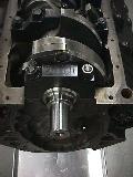
The Oliver 2-bolt front main. You can also see the second main that is a 10 degree splayed design. Also the axially installed mallory metal is visible in the crankshaft counterweight...that makes the crank internally balanced. |
 |
Front view of the shortblock assembly. |
 |
A look at piston #1 in the shortblock assembly. You can see the valve pocket reliefs cut into the top of the cylinders. Details make all the difference. |
 |
Here you can see the porting to the oil passage on that beautiful Oliver rear main. |
 |
The cam sheet for the first experimental cam that Comp Cams ground. It has the same exhaust lobes as intake and should show great normally aspirated power. |
 |
This is the cam sheet for the second experimental cam that Comp Cams ground for us. It has bigger exhaust lobe and might show big gains with the nitrous. We are hoping that it makes nearly the same power as the other Comp Cams cam without the nitrous, and if so, will be the one I run in the street. |


